In today’s world of dental technology, we often see that one of the biggest selling points for CAD/CAM systems is that they are “open.” So what does that mean exactly? In the case of dental CAD/CAM systems it means that at some given point you can export an industry standard file format, the STL file, and import it into another company’s system. Depending on the system they may be more or less open. For instance, one system may allow you to export an STL after scanning or designing, while another system will only let you export your final design. In other cases, you may have to pay a fee to open the system. No matter what “open” system you use they all use proprietary formats on the back-end. The reason for this is that in the 30 years since the STL file format was created, there have been many advancements in how 3D objects are represented. Proprietary formats tend to be much smaller in file size compared to the same file as an STL. They may also include information that an STL file can’t represent, like surface colors or textures.
Not All STL Files Are Created Equal
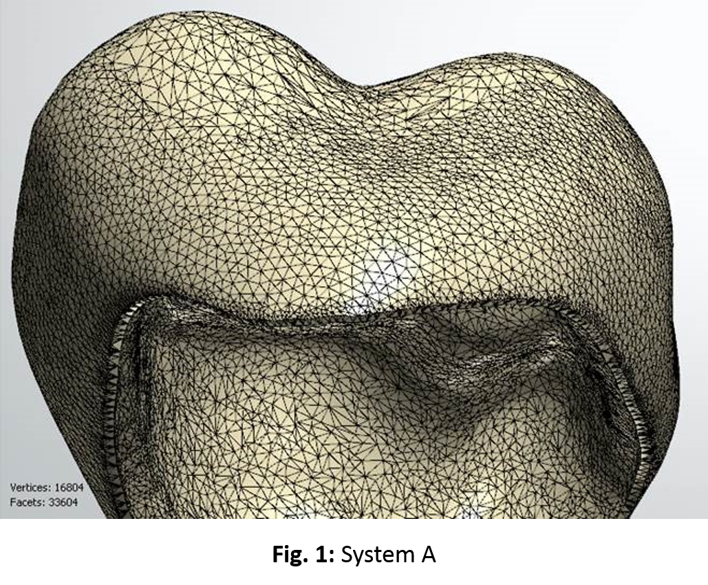
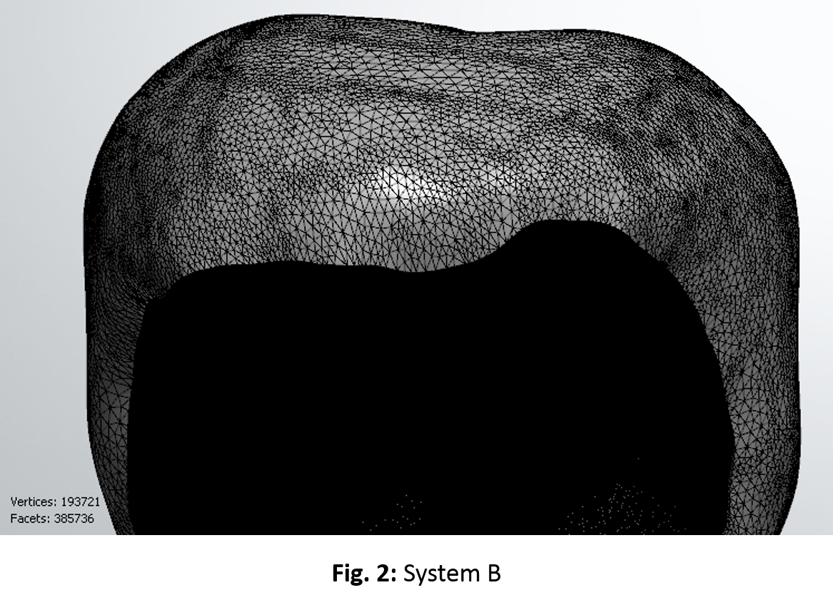
Now that we understand a little about what an “open” system is, let’s take a look at a comparison between two STL files exported out of two different CAD systems advertised as being “open”. In this comparison, the two different systems will only be referenced to as “System A” and “System B.” First, let's take a look at the triangle mesh of each file side by side, as seen below.


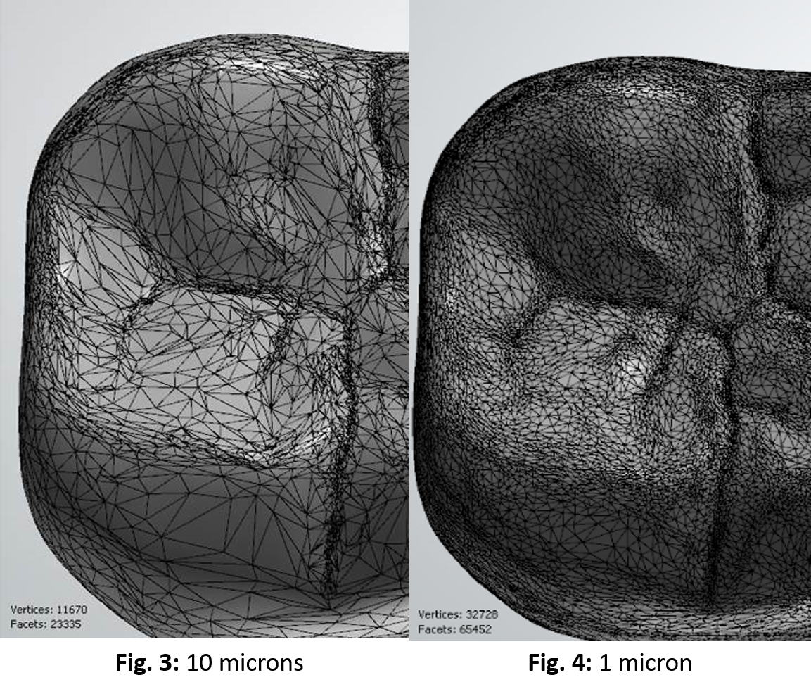
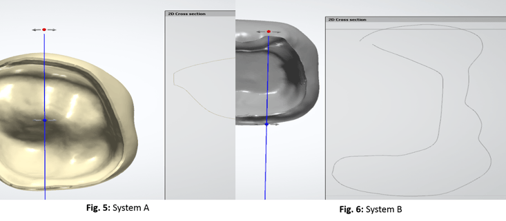
System A’s file (Fig. 1) reveals a very balanced distribution of triangles while System B (Fig. 2) shows a moderate distribution on the outside, but on the internal the triangles are so densely populated that you can’t tell the difference between them. When analyzing the total triangle count between the two files we find that System B’s STL has 11.5 times the triangles for the same size restoration. This means the file size is needlessly large and will be difficult to work with when imported into other “open” systems. You might be thinking, “they’re both STL files, so shouldn’t they be more similar?” The answer is, even though the STL file format describes the structure of the file, the algorithm that generates it determines the density of surface triangles. Both systems developers have taken a different approach on how they translate their proprietary CAD model format to STL. In the case of our example, System A optimized their algorithm to only use as many triangles as necessary to accurately describe the surface, where as System B has taken a maximum triangle approach. To give you a real world idea of how much unnecessary data there is in the file from System B, I went a step further and used a mesh editing program called 3DReshaper to perform mesh decimation. This allows you to specify a standard deviation from the original surface file and then the system will remesh the surface attempting to reduce the triangle count as much as it can while staying within the specified tolerance. By allowing for a deviation of only 10 microns (Fig.3) I was able to reduce the triangle count by 96%. I tested it again with a deviation of only 1 micron (Fig.4) and was still able to reduce the triangle count by 85%.

Now that we have looked at triangle count and file size, lets look at surface mesh quality. In this part of the comparison we have done a 2D cross-section of the two files in question. In System A’s image (Fig. 5) we can see that the surface is one continuous mesh. When we look at System B (Fig. 6) we find that the mesh is broken into two separate meshes right at the margin line. We also clearly see a large hole between the meshes output from System B. These holes vary from 10 microns all the way up to 100 microns on the files that we have analyzed. This issue can be much more problematic than the file size issue. When trying to manufacture the file from System B you’ll have a much harder time being successful. Milling software may do alright as long as the hole occupies a vertical plane where it can’t be seen for tool path processing. 3D printing on the other hand would lead to a 100% failure rate without using 3rd party software to repair the mesh and make it watertight. Many 3D printing software's have mesh repair features built in for this reason but when closing a hole this large it will be hard for it to create a surface that closely resembles that of the prep. This would lead to mandatory manual adjustment to get acceptable fits.

Conclusion
In conclusion, we can clearly see that although both files share the STL file extension and structure, they are quite different. In several cases the differences are extremely problematic for communication between “open” systems. So now that we know that all STL files aren’t created equal we can approach the myriad of “open” systems on the market with a little more fire power. Whether you’re looking for a new system or just wondering about compatibility between your system and another, don’t settle for the simple answer of, “Yes, it’s an open system, it accepts and exports STL files.” Ask for specifics on costs to open the system and examples of compatibility with other systems you know you may have to work with. This way you won’t be left hanging with the case of the unequal STL.


Leave a comment