


Section I: Introduction
When you think about the future, what comes to mind? If you were a youth in the early 60s, perhaps you think of the Jetson’s flying cars, jetpacks, and robot servants; if you were a child in the late 70s, perhaps you remember Star Wars’ light sabers, X-wing fighters, and robot sidekicks that will help you defeat The Empire; or if you were a kid in the early 90s, perhaps you recall The Next Generation’s warp drive, transporter technology, and replicators. Though we may not yet be in the future predicted by these writers, 3D printers are a step in the right direction.

In its early stages, 3D-printing is miles away from the ease and convenience of replicator technology. Instead of just telling a computer what you want and having it create it for you in a few seconds, you need to find or create an appropriate file to print… and determine the appropriate print settings… and ensure the appropriate support structure… and wait a few minutes to hours depending on how big the object your printing is to see if you got it all right. If not, you need to start over and continue the trial and error process.
Fortunately, Whip Mix’s R&D and technical specialists have struggled through the bugs and issues to create resins and material files that should work in most cases. There are, of course, prints we cannot predict. For instance, if you want to use our model material to print out something non-dental—a bust of your face, for instance—you will probably end up with a failed print.
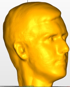
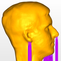
Side profile of one handsome author.
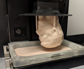
You can imagine my disappointment when I tried printing this and found a blob-shaped solid in the printer’s vat instead of a blob-shaped solid on the printer’s build plate. But I am no stranger to failed prints and disappointments, and, over my four years working at Whip Mix, I have learned and would like to share tricks that may help you print heavy objects like busts and aid in your understanding and success rate with 3d-printed, dental materials.
Section II: Burn-In Layer and Adhesion
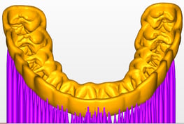
The most important layer in the print is the first one. A good burn-in layer is the foundation upon which the rest of your print builds and must, therefore, stick well to the build plate. That’s why it is very frustrating to print a very tiny die or a very large model and find it missing from the build plate. In these instances, what can you do to fix this?
Let’s start with the die. Dies are typically printed directly on the build plate to print the objects as quickly as possible. A die, however, has a small surface area on the build plate and a larger section growing from there. As the die prints, the weight of the material grows until the tiny surface area on the build plate cannot support it anymore, and it falls off.
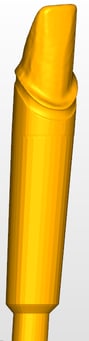

A close zoom in of a die with a very tiny contact point (~7 mm2).
When all else fails, you may try to add supports. But supports actually decrease the total surface area connected to the build plate, so, if the die failed before, you may expect the die to fail again.
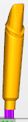
With these supports, our total surface area is ~2 mm2.
The solution to this problem comes from a setting called “Shadow” in Asiga Composer and “Support Base Thickness” in Alpha 3D.
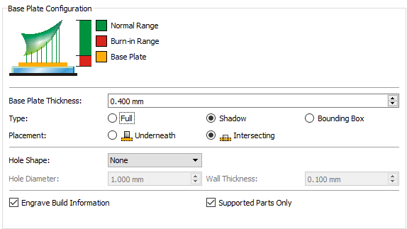
The settings shown in Asiga Composer. Make sure to set the “Base Plate Thickness” between 0.2 and 0.4 mm, select “Shadow”, “Intersecting”, and “Supported Parts Only”.
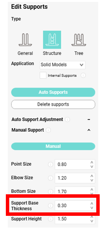
The equivalent setting in Alpha3D. Make sure the “Support Base Thickness”
is between 0.2 and 0.4 mm.
These settings create a larger surface area on the build plate for the supports and thus our die to stick to and gives your die the best chance of success. Of course, it uses a little more resin—in the case of this, a 20-mm cylinder with 0.4 mm thickness uses about ~0.00013 L—but this amounts to pennies and saves you from a massive headache of having to potentially re-print the file.
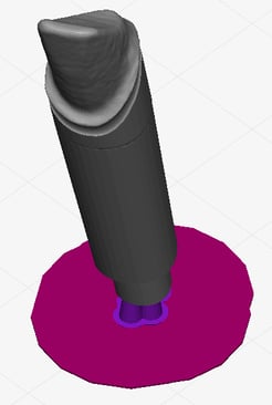
An example of a “Shadow” on a die.
Before moving on, it is worth answering another question—even if the shadow sticks to the build plate, what keeps the die on the supports if there is not a lot of surface area to hold it there? Resin-to-resin bonds form a polymer network far stronger than resin-to-metal bonds. Therefore, we can get away with less surface area because those points of contact are stronger.
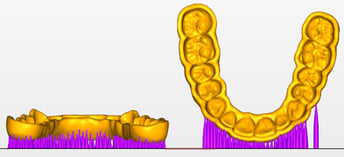
Now you know a trick to get tall objects with small surface areas to stick to the build plate. But what do we do about large objects like a large upper model or your head? Our solution here is very similar—the object comes off the build plate because its weight (in conjunction with the printing forces) exceeds the adhesion force between the object and the build plate. Size does not change the solution, just the scale. So, in most cases, you can simply place the object on supports and create a shadow and it will print fine. But, in the case of the bust, you will open up the printer to find the shadow and the supports on the build plate and a blob taunting you in the resin tray.
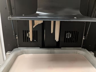
“You will never be able to print it, you fool,” the printer sneers.
For this example, we have to understand why the print failed. Our failure was not on the build plate, so we are not dealing with adhesion to it. Instead, our model failed to attach to the supports. So, despite all the good things I said earlier about resin-to-resin bonds, these small connections are not strong enough to sustain the weight of both this incredibly large object and the printing forces.
One possible solution to this problem involves changing the contact width of the supports. Whip Mix R&D and its technical specialists choose supports we believe will work for most applications of our resin but most is not all. Increasing the contact width (in Asiga Composer) or the point size (in Alpha3D) may help in some cases but is not necessarily guaranteed. This is likely an option for most dental models. But, in the case of this giant head, we have to try something else. We need to increase the total surface area of the model by either increasing the number of places in contact with the build plate or increasing the strength of those contacts.
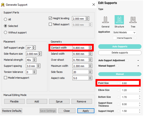 Here are the locations in which you can change the contact width of supports. Whip Mix has created values we believe to work in almost every dental situation, so please use the default settings first.
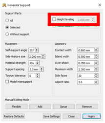
If we turn off height leveling (in Asiga Composer) or manually place our supports in Alpha3D, we can attach the object to the build plate (and thus our shadow) while still keeping all necessary parts supported which comes with the benefit of increasing the part’s total surface area.
Now, if we go back to the settings in Asiga Composer, we can select “Full” instead of “Shadow” which will create a shadow the size of the build plate. This maximizes the adhesion as the shadow is as large as possible and the part is fused to it. On Alpha3D, this cannot yet be done by software, so you can just create a 0.4-mm rectangular prism and increase the length and width to cover the build area.
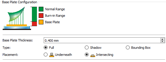
The settings shown in Asiga Composer. Make sure to set the “Base Plate Thickness” between 0.2 and 0.4 mm, select “Full”, and “Intersecting”.
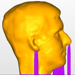
And, after a few hours, our print comes out looking fine.
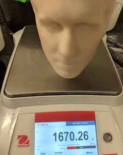
The finished head weighing in at ~3.7 lbs or ~1.7 kg. If this can stick to the build plate, anything can.
Section III: Suction Cup Forces and Print Times
Rather than all of the complicated steps we took previously, one may suggest modifying the head to make it hollow. This will save money by using a lot less resin, but, unfortunately, does come with unforeseen consequences.
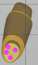
Recall we mentioned “other printing forces” when talking about causes of failures in the previous section. One of these forces is the suction force. When an object is printed hollow, the outer walls keep resin trapped inside the model and create a suction force when the print head tries to move up. This force, depending on the size of the object and the number of them, can be quite significant and leads to longer print times as the print head has trouble moving, deformed prints caused by the forces working on the thin walls, and, in some cases, even print failure as parts get ripped off the build plate.
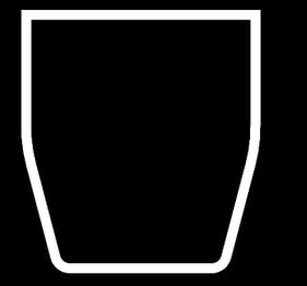
The walls on this object act as a suction cup creating additional pressure
when the print head raises up.
To solve this problem, one can either print the object solid or add drainage holes to the base of the model. In all dental cases I have seen, the latter is enough. But, in the case of large objects (like my head), the drainage holes at the base of the model will inevitably be out of the resin as the object is built up and the suction forces will start to build up again because resin cannot travel up to the holes. Therefore, if you want to print a large, hollow object, you would need to make holes repeat every so many centimeters to allow additional resin to flow out. Being conscientious of this will help keep your print times down and keep your parts looking good.
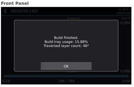
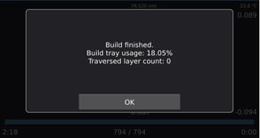
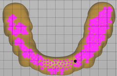
On the left, we have the print time for an object with a large amount of suction force, and, on the right, the same object with holes in it. Notice the print time is decreased by about 2/3 by adding the drainage holes, and we have stopped traversed layers from occurring.
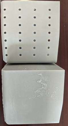
In the image above, the left part is subjected to suction forces, whereas the drainage holes in the object on the right allow resin to flow out. Notice how bad the quality of the printed part is on the left.
Section IV: Print Orientation and Maximizing Physical Properties
Now consider the print process. When printing on a DLP or LCD printer, the entire XY-axes of a layer is printed at once. The print head lifts up, goes back down, and then cures the next layer. The entire XY-axes of this second layer is completely formed from the light and an extra dose goes into attaching the first and second layer together. But this process comes with its drawbacks. In the XY-direction unreacted material finds unreacted material easily to form strong bonds, but, when it attaches to the previous layer, there are less unreactive spots on the previous layer to which to attach. In short, the two layers are not held together as tightly (on the Z-axis) as the individual layers are (on the XY-axes). These directional differences lead to anisotropic properties.
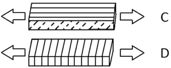
Credit to https://www.tetonsim.com/blog/post/introduction-to-anisotropy-of-3d-printed-parts for the lovely picture. Notice how forces pulling apart the top picture will have a harder time separating the layers (on the XY-axes) than the bottom picture in which the forces are pulling apart layers on the Z-axis.
When printing out something structural—a tooth, a splint, a surgical guide—it is important to consider how the device will be used and from which direction the force acts on the object. In general, the device is strongest when the force acts parallel to the direction the object was printed in (or perpendicular to the lair lines).
Section V: Choosing the Right Location for Your Supports
This does not mean, however, you should always consider strength when orienting your part. Sometimes accuracy takes priority. Take, for instance, a crown shown below:
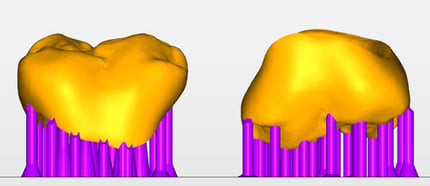
Parts oriented in a way that would give the best mechanical properties against chewing. But this not the right way to print the crown.
From the previous section, one might place supports on the bottom of the object since that would give the device its greatest mechanical properties. But, of the two orientations shown above, which is better?
Supports always decrease the accuracy in the area they touch because they modify the surface to which they are attached. Since we have to add supports to our crown, we have to choose to place them on one of two sides shown above. And the most important surface is the one sealing against the implant because if it does not fit, the device does not work.
Unfortunately, printing this way gives us a crown that fits a die but loses a lot of anatomical data. But we can improve it by printing on a slight angle. By doing this, we may decrease the maximum strength of the device slightly, but we more than make up for it by decreasing the total number of supports and retaining the anatomical detail.
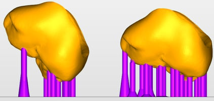
The crown on the left is angles at 45 degrees and the one on the right is at 30 degrees. Notice there are fewer supports as you change the angle. Check the IFU for the manufacturer’s recommendation.
The same principles apply to printing fun objects for yourself. For the best finish, the fit is the most important part of the print so prioritize connecting surfaces, minimize the number of supports by angling the object in a way that the part becomes self-supporting (does not need supports to print), and, finally, consider placing supports away from a surface you will frequently see (on the front of the model).
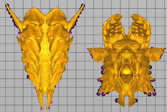
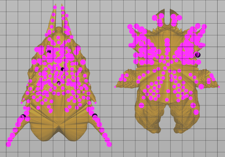
In the example above, the model does not have connecting surfaces, so we are concerned with minimizing the number of our supports and ensuring the best, over-all looking model. Printing the supports on the back of the monster’s head instead of on its neck not only minimizes the number of supports but allows the front to retain its design. Go with the orientation on the right.
Section VI: A Brief Discussion of Light Bleed Through
From the previous section, one might think printing with the fewest supports possible is always the best option and that they should print their splint at a 90 degree angle so the number of supports is minimized and the anatomy is conserved. (This person has already forgotten the part would have its weakest mechanical properties when printed in that orientation, but I digress.)
But there are problems printing with angles as well—namely, light bleed through. Imagine printing the letter “H” but on its side. Say this takes three layers to print—one layer is the bottom line, the second layer is the gap with the column in the middle, and the third layer is the top line. On layer two, light turns off on the edges. But on layer three, the light turns back on at those edges. If there is light bleed through, light will cure through layer three and back to layer two, which will turn our “H” into a block.
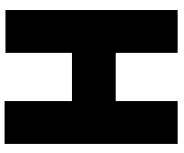
Layer 3
Layer 2
Layer 1
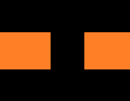
The object on our left is our sideways letter “H”. If there is light bleed through, the orange areas will cure when the third layer prints turning the “H” into a block.
This light bleed through is caused by the resin not blocking light. Normally, this problem is worse in clear materials than opaque ones but is present to some extent in all materials. In short, this is a property of resins and cannot be removed.
Instead, we can minimize its impact by selectively angling our objects in the slicing software. In the case of the splints shown above, 0 degrees (parallel to the build plate) will have the least amount of light bleed through. As we increase the angle, we introduce more places for the light to bleed through. Most manufacturers of clear resins will suggest an angle for the resin to print at to avoid this issue but, in general, anywhere from 0 to 60 degrees seems to be okay.

A splint angled at 45 degrees has more supports than one at 90 degrees but will not suffer from the same degree of light bleed through.
Section VII: Conclusions
To summarize key points of this article, 3D printing is complicated. There is not a one-size fits all solution. Materials printed have anisotropic properties making them weaker in one direction than another, but we cannot always aim to maximize physical properties because sometimes accuracy is more important. Then support placement becomes key, and we must decide on a way to place supports minimizing their number, decreasing the effects of light bleed through, and maximizing the part’s accuracy. But all of these settings do not matter if can’t keep your part on the build plate anyway. Hopefully you have learned some ways to avoid problems and increase the success rate of your prints. 3D-printing may not yet be as easy to use as replicators, but their promise evokes those long dormant, childhood memories of the future.


Leave a comment